Transformers are an essential part of our daily lives. We use transformers in power stations, substations, and homes. A transformer is a device that transfers electrical energy from one circuit to another via electromagnetic induction. The transformer core is one of the main components of a transformer. Engineers design the core to magnetically link the windings and provide a low reluctance path for the magnetic field. They must also create the core to minimize eddy current and hysteresis losses. In contrast, the core acts as a coupling between the windings. But what are the components of the transformer core itself? Let’s delve into the details.
Three Essential Components of a Transformer Core
The three essential components of a transformer core includes: the core, the primary winding, and the secondary winding. A ferromagnetic material, such as iron or steel, creates a magnetic field in the core. The primary winding is the input winding, receiving the electrical energy from the first circuit. The secondary winding is the output winding, delivering the electrical power to the second circuit.
In addition to the core, primary, and secondary winding, larger transformers may have other components, such as insulation, transformer oil, cooling arrangements, protection relays, and an enclosure.
- Insulation protects the windings from electrical shock.
- Transformer oil cools the transformer and insulates the windings from each other.
- Cooling arrangements remove heat from the transformer.
- Protection relays protect the transformer from overcurrent, overvoltage, and other faults.
- An enclosure protects the transformer from the elements and physical damage.
Core
Transformers have a core at their center, which supports the windings. The core provides a low-reluctance path for the electromagnetic flux. It is comprised of thin sheets of premium grain-oriented steel separated by thin insulating materials. The carbon content of the core steel is kept below 0.1% to reduce hysteresis and eddy currents.
The two main types of core constructions are core type and shell type. Core-type transformers have a core that surrounds the windings. Shell-type transformers have windings that surround the core.
Windings
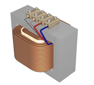
Image Attribution: https://en.wikipedia.org/wiki/Transformer
Transformer manufacturers wind several copper or aluminum wire coils to form the windings. They insulate the coils from each other and the transformer core. The number of turns in each coil determines the voltage of the winding. The transformer connects the windings to the input and output.
Factors such as the current rating, short circuit power, temperature rise, impedance, and surge voltages of the transformer determine the type and configuration of the windings.
The primary winding connects to the input voltage, and the secondary winding connects to the output voltage.
Transformers can divide the primary and secondary windings into the high voltage (H.V.) and low voltage (LV) windings. The transformer connects the H.V. winding to the high-voltage input. The transformer connects the LV winding to the low-voltage output.
The voltage range and the current carrying capacity of the winding determine the winding to use.
Insulation
Power transformers use cellulose (paper/pressboard) and oil as insulation. Copper is used to make windings because of its high conductivity and flexibility. These components protect the transformer core and the primary and secondary windings from each other.
Insulation is required between the core and the windings and between each winding turn and the tank. The insulators must withstand high temperatures, have good mechanical properties, and have high dielectric strength.
Transformers can be severely damaged if the insulation fails. Transformer manufacturers use synthetic, paper, and cotton materials to insulate transformers.
Tank
A transformer tank is a container that holds, protects, and cools the windings and core of an electrical distribution transformer. It also serves as a reservoir for the transformer oil and supports all other accessories. The tank protects the core and windings from the outside environment, and it helps to dissipate heat generated by the transformer.
Transformers typically have tanks made of steel or aluminum. Steel tanks are more common, but aluminum tanks are lighter and can help to reduce stray losses. Transformer manufacturers shape rolled steel or aluminum plates into tank bodies. Lifting hooks and cooling tubes are added to the tank body.
Here are some additional details about transformer tanks:
- The tank must be strong enough to withstand the weight of the transformer and the forces generated during operation.
- The tank must be leak-proof to prevent the loss of transformer oil.
- The tank must be insulated to avoid electrical shock.
- The tank must be easy to access for maintenance and repair.
Transformer tanks are an essential part of transformers, and they play a vital role in the operation of these devices.
Terminals and Bushings
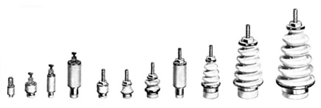
Image Attribution: https://en.wikipedia.org/wiki/Bushing_(electrical)
Transformers have terminals that connect incoming and outgoing cables. These terminals are usually mounted on bushings and connected to the ends of the windings by wires.
Bushings are insulating devices that provide a barrier between the terminals of a transformer and the tank that contains it. They are typically located on top of the transformer tank and provide a secure path for conductors that connect the terminals to the windings. Manufacturers make bushings of porcelain or epoxy resin.
Transformer Oil
Transformer oil provides insulation between the conducting parts, helps dissipate heat, and detects faults. Manufacturers make transformer oil from hydrocarbon mineral oil, a mixture of aromatics, paraffin, naphthene, and olefins. It has a density of 0.96 kg/cm3, a flashpoint of 310 degrees Celsius, and a relative permeability of 2.7.
Oil Conservator
The oil conservator tank provides space for transformer oil to expand and contract as the ambient temperature in the main tank fluctuates. It is a cylindrical drum mounted on top of the main tank. It has a Buchholz relay mounted on the pipe that connects it to the main tank and a level indicator to show how much oil is in the tank.
Breather
A breather is a device that is attached to the tank of a liquid-immersed power transformer. It prevents moisture from entering the oil. The breather is a cylinder filled with silica gel, which absorbs moisture from the air. This is important because water can react with the insulating oil and cause internal faults. The breather helps to keep the air dry, which protects the transformer from damage.
Radiators and Fans
Depending on their size and power rating, various cooling methods are used to cool transformers. Small transformers, such as dry-type transformers, are typically cooled by natural air convection. Larger transformers, such as oil-immersed transformers, require more sophisticated cooling methods.
Oil-immersed transformers use a combination of natural and forced cooling. The transformer oil absorbs the heat generated by the core and windings. The oil then circulates through the radiator, cooled by the air. In larger transformers, cooling fans increase airflow through the radiator. The kVA rating, power losses, and level of cooling requirements determine the type of cooling used for a transformer.
Explosion Vent
An explosion vent is a safety device that releases oil and air gases from a transformer in an emergency. It is typically a metal pipe mounted above the conservator tank with a diaphragm at one end.
The diaphragm allows oil and air gases to escape from the tank safely at relatively low pressure. This prevents the pressure in the tank from building up to dangerous levels, which could cause an explosion. Explosion vents are an essential safety feature that can help to protect people and property from the dangers of transformer explosions.
Tap Changers
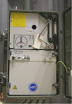
Image Attribution: https://en.wikipedia.org/wiki/Tap_changer
A tap changer is a device used to control a transformer’s output voltage. It does this by changing the number of turns in one winding, which affects the transformer’s turn ratio. There are two types of tap changers: de-energized tap changers (DETC) and on-load tap changers (OLTC).
- De-energized tap changers (DETCs) can only operate a transformer when it is not energized or “offloaded.” Tap changers can spark and catch fire during a transformer energized state when their electrical connections are made and broken.
- On-load tap changers (OLTCs) can operate a transformer while it is energized or “on load.” This is because they use a unique switching mechanism that prevents sparks from forming. OLTC tap changers are more expensive than DETC tap changers. Still, they offer the advantage of adjusting the transformer’s output voltage without interrupting service to the load.
In addition to DETC and OLTC tap changers, there are also automatic tap changers. Large transformers typically use automatic tap changers to adjust the output voltage to compensate for load or line voltage changes. Large transformers typically use automatic tap changers to adjust the output voltage to compensate for load or line voltage changes.
Buchholz Relay
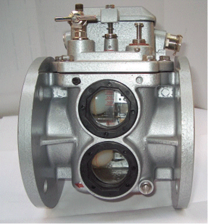
Image Attribution: https://en.wikipedia.org/wiki/Buchholz_relay
Buchholz relays are safety devices installed in oil-immersed transformers with a rating above 500 kVA. They are used to detect and protect against internal faults in the transformer.
Buchholz relays work by sensing the presence of gases produced when the transformer oil breaks down due to a fault. These gases include methane, carbon monoxide, and hydrogen. When Buchholz relays detect these gases, they activate an alarm and a trip circuit. The alarm circuit alerts the operator of a potential problem, and the trip circuit interrupts the current flow to the transformer, which helps prevent a major failure.
Buchholz relays are an essential safety feature for oil-immersed transformers. They can help to prevent significant failures that could cause fires, explosions, or other damage.
In conclusion, the components of a transformer core are essential for the proper functioning of the transformer. The core provides a path for the magnetic field to flow and helps insulate the primary and secondary windings from each other. By understanding the components of a transformer core, you can better understand how transformers work and how to select the suitable transformer for your needs.
Innovative Solutions Exceeding Industry Standards
At Corefficient, we understand the critical role that transformer cores play in the performance and longevity and efficiency of electrical systems. That’s why we prioritize innovation and precision engineering to provide you with top-of-the-line transformer cores that exceed industry standards. If you want to learn more about our transformer cores, please get in touch with us. We happily answer any questions and help you select the suitable transformer for your application.
More on Corefficient
Our state-of-the-art, ISO-9001 certified center in Monterey, Mexico, houses a group of knowledgeable specialists who work tirelessly to provide you with first-rate support across North America and beyond.
Corefficient has worked hard to develop since 2016 and now offers high-performance electrical transformer cores and first-rate customer support. We provide increased core efficiency based on material choices, manufacturing techniques, and geometries. Please look at our transformer core services.
Call 1 (704) 236-2510 to immediately contact a Corefficient sales engineer!

